
TrueGrid® Pre-Processor
In addition to generating a mesh TrueGrid® can generate most of the non-geometric components of the model needed for pre-processing.
Loads and Conditions
Loads and conditions can be assigned to various parts of the model.
This includes:
|
|
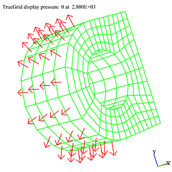
There are two ways to assign these loads and conditions to portions of the mesh:
- Make assignments to selected regions of the mesh in the part
- Make assignments to nodal or face sets in the merge phase
NOTE: there are numerous ways to create sets for this purpose.
Constraints and Boundary Conditions
With structures, a node can have a reduced set of degrees of freedom. Such reductions can be applied in the global coordinate system or an arbitrary local coordinate system. A special case is nodes placed on a symmetry plane. It is also possible to constrain a set of nodes so that they are forced to move together. Constraint equations tie nodal degrees together with an equation. ALE Smoothing Constraints can be set. Joints have properties where the movements of the nodes of a joint are coupled. Nodes along a stone wall or a symmetry plane with failure also have restrictions on the movement of some nodes.
|
|
With fluids, there are various boundary conditions such as an inlet, an outlet, or a wall, just to name a few. The list of possible boundary types is different for each fluids code. |
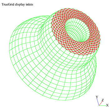
All of the these constraints and boundary conditions can be applied by selecting a region in the part phase. In many cases, they can also be applied to a node or face set.
Contacts and Interfaces
Some structural codes have a contact surface feature. In many cases, two opposing regions of the mesh must be identified. Also, these contact surfaces have characteristics that must be identified. In LSDYNA, one can couple shells and bricks by forming a set of fibers along the face of the brick elements. A cohesive feature can be applied to shells by automatically inserting shells with zero width (the cohesive element) between two shells elements.
The faces that form the contact surfaces can be identified in the part phase by selecting a region of the mesh. Alternatively, a face set can be selected for a contact surface.
Properties and Element Types
Most simulation codes have a set of properties associated with each material model. These material model properties and the associated element types can be selected. Then elements are assigned a material model. This can be done by either selecting a region in the part phase or by assigning the material model to an element set.
There are many element type options. Typically, a basic element type is selected as part of defining a material. For example, quad shell properties can be part of the material definition. And if a triangular shell is formed by collapsing a quad element edge, TrueGrid® would automatically change the element type, while keeping it in the same family, for this element. This principle caries over to hexahedron elements with degenerate edges that form prisms, tetrahedrons, and for some codes, pyramids. The default element order is linear (first order). It can be increased to quadratic (20 node hexahedrons) and triquadratic (27 node hexahedrons). Element types also include springs, dampers, point masses, beams, tracer particles, SPH, and DEM.
Sets
There are four types of sets: node, face, element, and polygon. Node sets are typically used to assign boundary conditions and some types of contact surfaces. A face set is a collection of element faces and can be used to assign loads and conditions including some types of contact sufaces. Face sets can also be used to form a surface. Element sets can be used to assign material properties and heat sources. An element set can also be formed to delete elements. A polygon set is used to form a surface. These polygon sets are formed from polygon surfaces or from face sets.
There are four basic ways to form a set: rectangular regions of a multi-block part, arbitrary regions selected by mouse, proximity to a surface or curve, or boolean operations (union, subtraction, intersection of sets).
Analysis Options
In order to run a simulation using a model from TrueGrid®, one must first identify the analysis options and other global properties of the model. Many of these options can be selected within TrueGrid so that the final output file from TrueGrid® can be imported to the simulation code, without modification to this file, and run.